Red Bull has taken over from Mercedes as Formula 1’s dominant force, based on what we saw in the recent triple-header. So what’s made the difference between the two cars?
With the way F1 regulations are going, I often wonder what new technologies the thousands of very clever people who work in the design and research areas of these teams can bring to the big world outside. Yes, the opportunity for that has always been limited, as parts on an F1 car have always been much too expensive to transfer directly to road cars, but the inspiration to exploit them and prove their worth has always been there.
What would Colin Chapman with his ground-effect cars, Gordon Murray with his driver-lying-down concept, fan car and refuelling, or Derek Gardner with his six-wheeled Tyrrell think of the current uninventive, draconian, overly-prescriptive regulations if they were sitting down to sharpen their pencils in preparation for the new season?
All that said, we still see differences between what the teams come up with. There are no major visual concept differences, but as is often said, the devil is in the detail, and that detail really does pay dividends.
Now, instead of seconds or even tenths of a second of improvement, the teams are looking for hundredths of a second. With this small return for all the effort of introducing a development package, it is difficult to really be sure if you have moved forward, stood still or actually gone backwards.
This is where Mercedes finds itself at the moment. The dominant team from the start of the season and a runaway championship contender has stumbled. Its development package introduced in Malaysia has confused it. Yes, it says the numbers all add up to a positive, but the drivers are finding the car more difficult and, with that, finding it harder to consistently extract the laptime from it.
On the other hand, Red Bull has done the opposite. It has come from a more or less disastrous start by its standards to be on pole and win the last three races. Yes, one was a sprint, which, as Max Verstappen said, doesn’t really count, but even so, it just shows that when it comes to introducing developments, there are two sides to any coin and only one (or should I say won) will come up trumps.
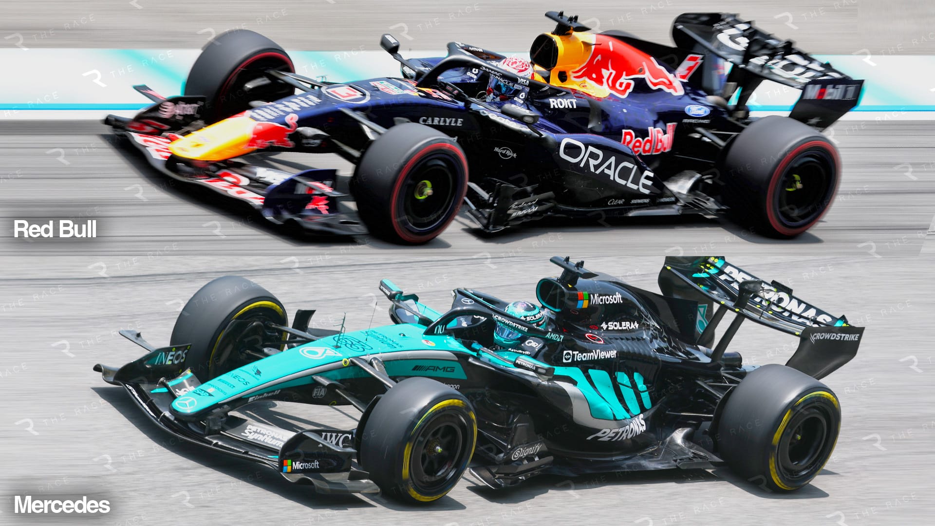
Starting at the front, let’s compare the Red Bull and Mercedes.
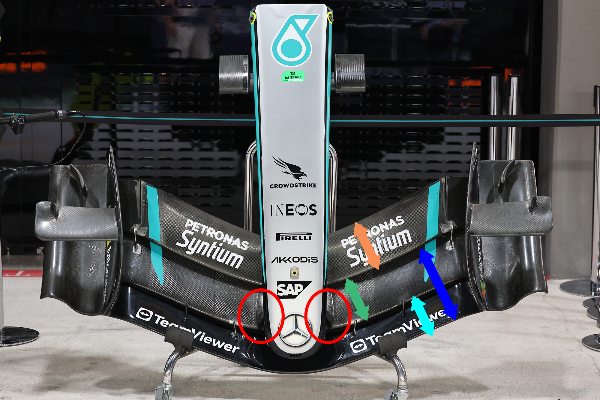
Mercedes and Aston Martin were, as far as I am aware, the only two teams to start the season with the front wing mounted on the second element (highlighted with the red ellipse). This meant that, for straight mode, only the third element (orange highlight arrow) was reduced in angle.
Overall, there is probably a small weight saving with this concept, but in general it has meant that the forward element is more of a flow-direction optimiser as opposed to a major downforce-producing device. I say that because the slot gap between the first and second elements is fairly close to where the lowest air pressure is on the wing’s underside. This low pressure creates downforce, basically it pulls the car towards the track. On the Mercedes concept, it will simply pull more airflow through that slot gap.
We can see here that the chord lengths of the three elements are not vastly different: forward highlighted with the light blue arrow, middle with the green arrow, rear with the orange arrow. They are also fairly constant in chord along their span.
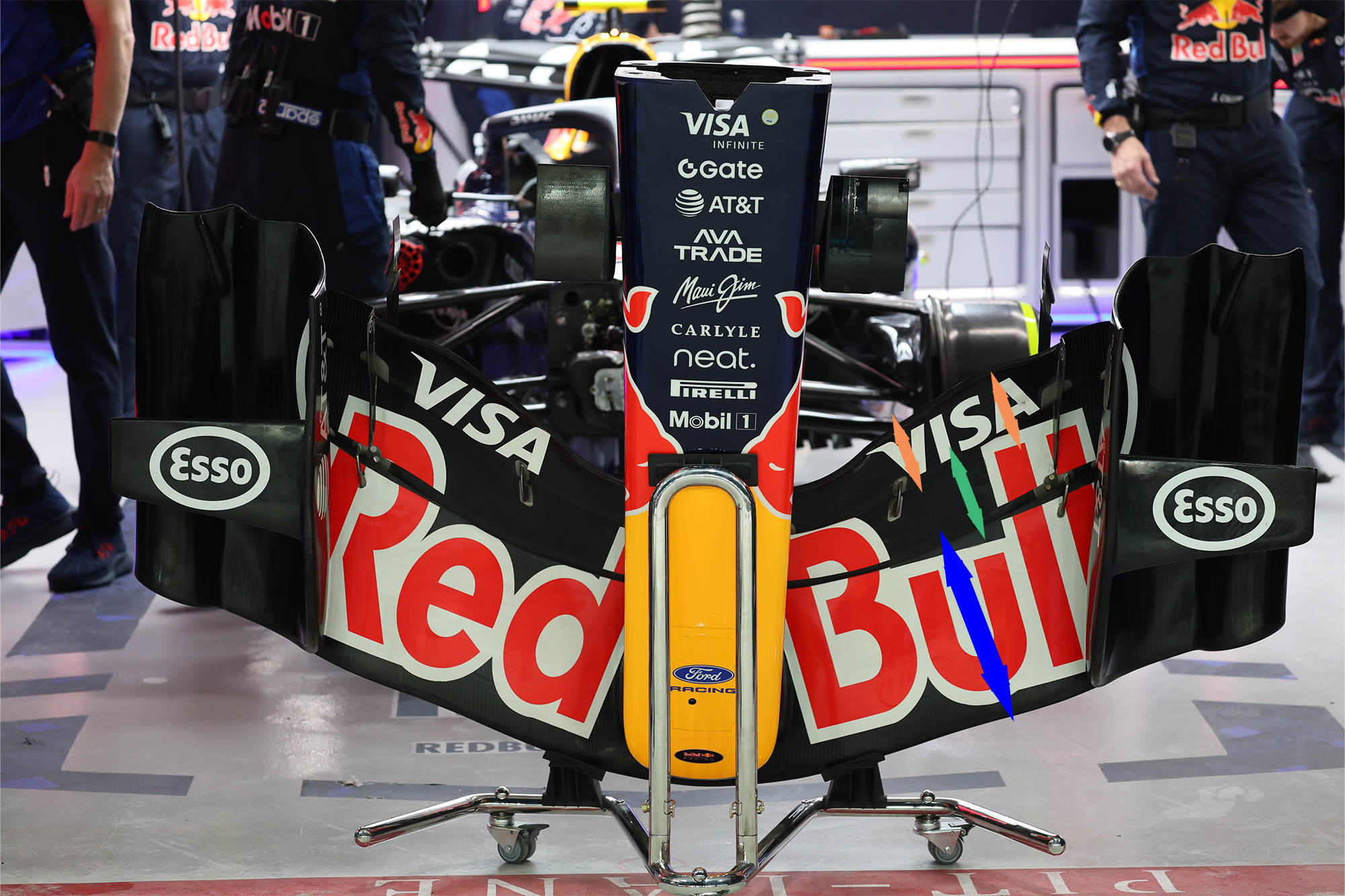
Red Bull, Ferrari and McLaren have all gone for the other approach: a much longer-chord mainplane, highlighted with the dark blue arrows. When in straight mode, they reduce the angle of both the second and third elements.
I have transposed that dark blue arrow onto the Mercedes front wing to show what I mean about the slot gap between the forward element and the second element being slap bang in the middle of the total chord length of its two forward elements.
The chord lengths of the second and third elements, highlighted with the green and orange arrows, increase going outwards. This means that there is less airflow direction change inboard and under the chassis, where the objective is to get the best and fastest mass airflow to the leading edge of the underfloor.
Also, on the Red Bull, the detail of the trailing edge of the endplates is more sophisticated than on the Mercedes. This should reduce the sensitivity when the front of the car is close to the ground under braking, in roll mid-corner and on corner exit when the outer part of the wing runs over the exit kerbs.
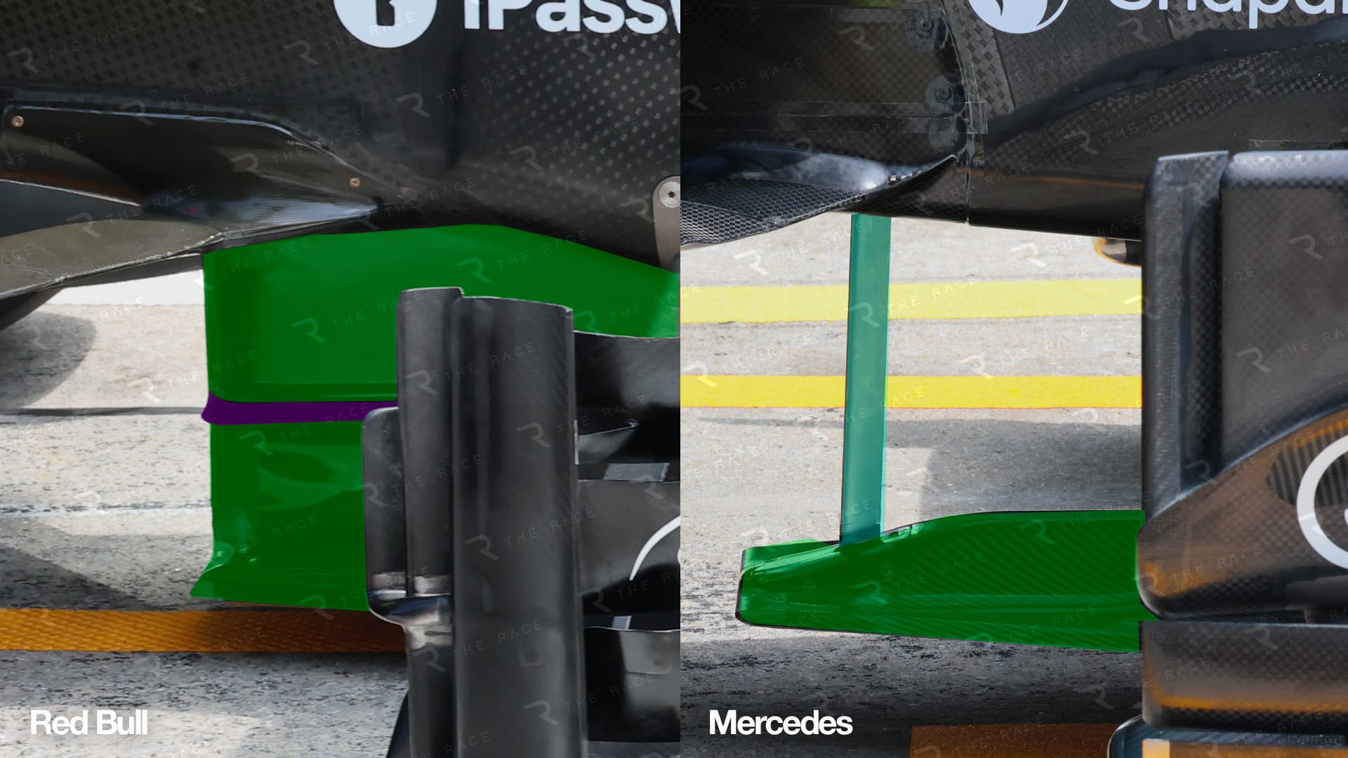
Moving on to the leading edge of the central section of the floor, the Red Bull floor mounting system (green highlight) basically splits the car into two halves. It also has a small vane (purple highlight) halfway up that mounting system to help tidy up the airflow coming off the central section of the front wing.
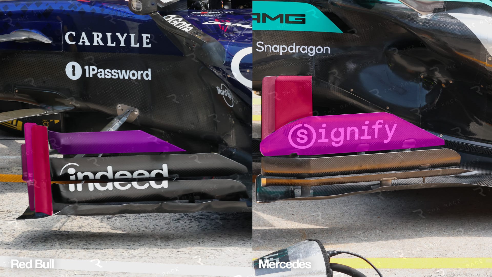
The bargeboard and floor plate area is similar but actually fairly different in how it treats the airflow that it is trying to manage.
Overall, there are a similar number of elements. However, Red Bull looks as though it is doing more to attempt to tidy up the front tyre turbulence (wake). F1 being an open-wheel formula, managing the airflow around the tyres, both front and rear, is critical to the car’s overall aerodynamic performance.
Also, the wheel blockage probably accounts for something like 40% of the car’s drag.
As the car passes through the air, it has to displace a serious volume of air. That displaced air tries to fill the void behind the tyres, so managing it and making sure it doesn’t detrimentally affect the other downforce-producing devices is basically what this bargeboard and floor plate area is about. Red Bull is doing more to attempt to manage that turbulence before it does what it can to generate downforce from the floor footplate, in effect the front corner of the floor.
Instead of having a simple downwash sidepod as most teams now have, Red Bull has retained the raised outer section, giving it a gully inboard which is very similar in profile to the Mercedes sidepod in side view.
This is to help manage the airflow over the sidepods and into that central area around the sides of the gearbox, as opposed to just generating more flow through the complete width of the coke bottle area. Doing this can improve the diffuser’s performance where it struggles most, in its central section.
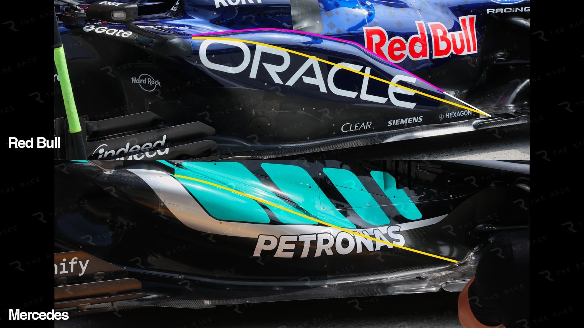
Red Bull also seems to have pulled off something of a controversial coup here, in that it has a very sharp trailing edge where the red highlight line turns to white.
The regulations define the minimum radii allowed on the sidepod’s upper corners. Most teams simply go for those minimum radii but with any regulation, it is about finding any grey areas. By having this sharper corner radius, as the airflow from the upper sidepod gully and the outer sidepod surface joins up, it will be travelling at different speeds, so basically along that sharp corner it will instigate a vortex which concentrated correctly, will travel along the inside of the rear brake ducts, generating higher levels of downforce on the turning vanes that are mounted on those brake ducts and in turn improve the performance of the diffuser.
The yellow highlight line is basically the Mercedes sidepod’s side profile.
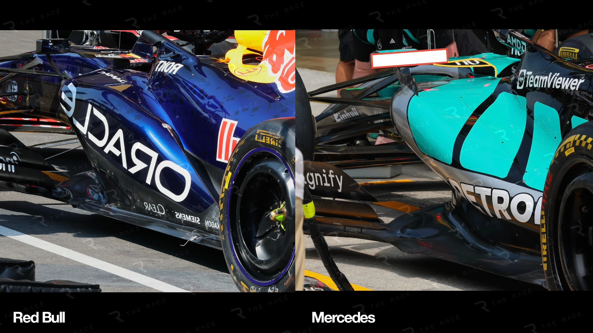
We now move on to the area in front of the rear tyre contact patch. This is again about managing the airflow around the rear tyre, especially the tyre’s contact patch area.
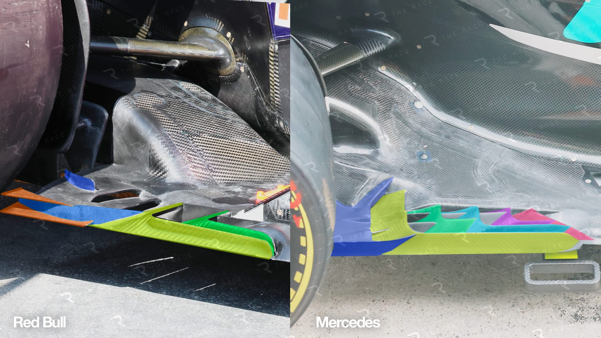
As the tyre rotates on the track surface, you get what’s called tyre squirt. It goes both inboard and outboard. Outboard, you can basically let it do what it wants to do, but inboard tyre squirt can be detrimental to the performance of the diffuser and, in turn, the complete underfloor.
The detail and the philosophy in this area are quite similar. The Red Bull vent system seems to be further forward and, as you can see from the slot shadows on the ground below the floor, the slots lead naturally to the inside of the rear tyre contact patch.
Even though these are slots in the floor connecting the top surface to the underside, the objective is to actually reduce the spillage from the top surface going underneath the car. They act like a sealing system by connecting that fairly high-energy tyre squirt to the void behind the tyre’s contact patch. In turn, that airflow that would normally be pulled underneath the car by the low pressure on its underside is also pulled around the tyre contact patch.
Gone are the days when the diffuser was a simple ramp to a rectangular exit area; now it’s a multitude of vanes with strategically placed openings. Not to criticise Mercedes, but the Red Bull system seems to have just that little bit more detail to its elements. The other thing I would question on the Mercedes is the inner extension that connects the trailing edge of the diffuser to the beam wing, if it can be called that, highlighted in purple.
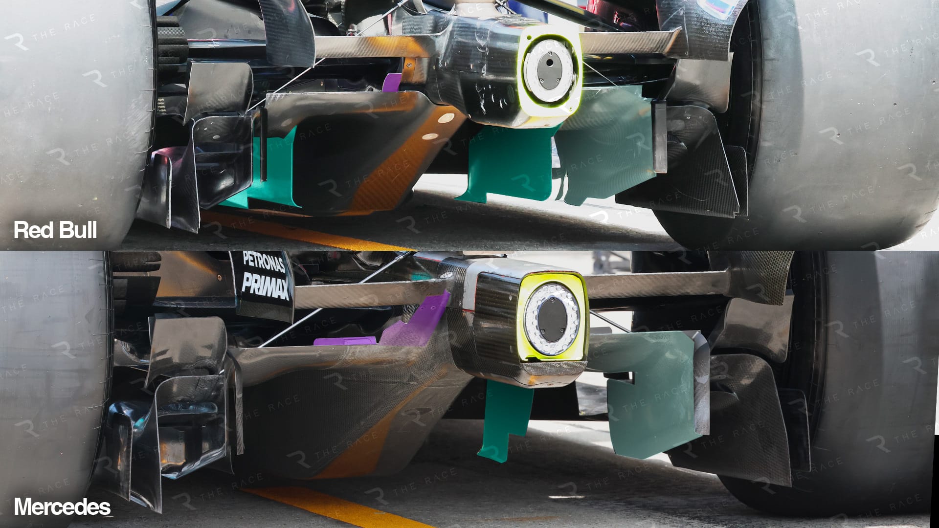
This inner section of the diffuser is furthest away from any influence from airflow structures coming from any other components, and because of that it can be tempting to maximise the performance in that area. However, when the car is close to the ground or the ambient and/or track temperature increases, the airflow in that area gets a bit lazy.
When that happens, it’s very easy to induce airflow separation, especially along the junction of the inner vertical surface and the diffuser’s upper surface.
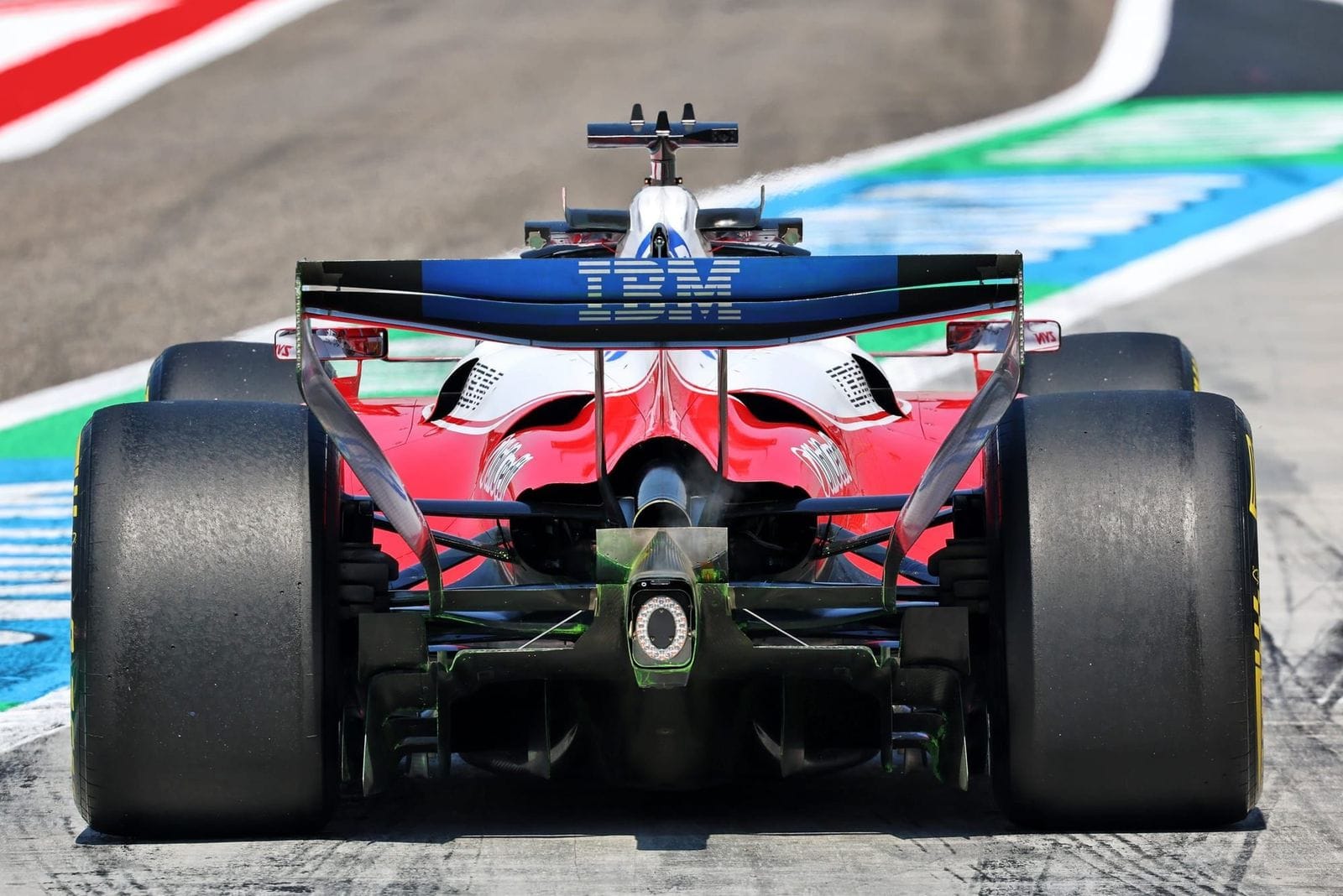
Ferrari was the first to introduce the exhaust exit ramp. After many column inches about how it had managed this within the regulations only because of its differential position, most of the other teams have achieved more or less the same solution. Basically, the regulations call for an exhaust outlet of a minimum size. It has to be round, and the exit angle is also defined, all of which is to reduce the potential for exhaust blowing.
However, where there is a will, there is a way. One of the arguments was that mounting brackets weren’t controlled in the regulations. Whatever the reasoning, the objective is the same: having something behind the exhaust outlet simply redirects the exhaust flow upwards and, as part of the exhaust outlet is blanked off, it increases its velocity.
On full throttle and at reasonably high revs on corner exit, both of these will improve the rear downforce from the rear wing and consistency in that central section of the diffuser that I spoke about suffering from separation problems earlier.
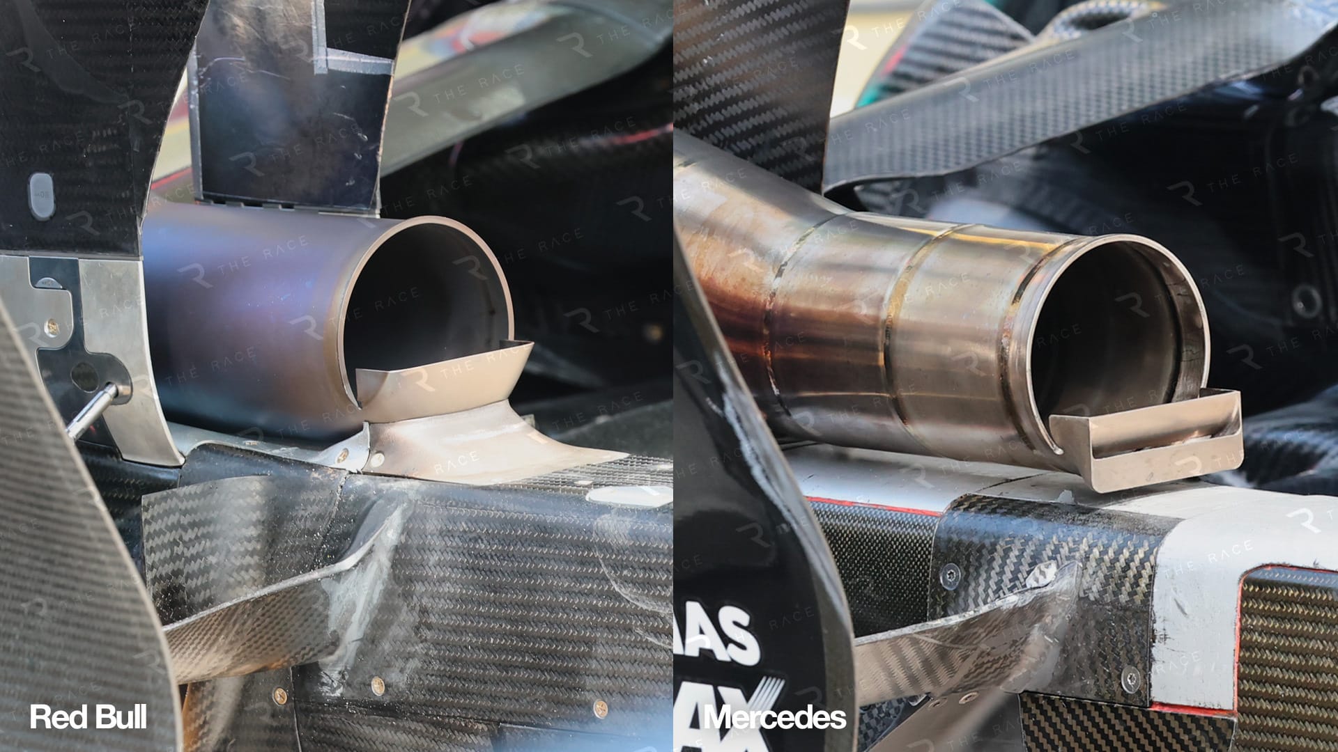
Many times I say the devil is in the detail, so I suppose you could say that the twin element vane on the Mercedes should be a little better than the single element version on the Red Bull, but in this case I don’t think it really matters. Basically, it is a blanking plug that alters the velocity and direction of the very inconsistent and turbulent exhaust gas flow, so adding the component does most of the heavy lifting and optimising the detail would give a very small return.
If I were part of the decision-making group at the FIA, I would have banned it from day one. The reasoning would be that you couldn’t see the required opening, it wasn’t round as required, and the last section wasn’t within the required angle.
Conclusion
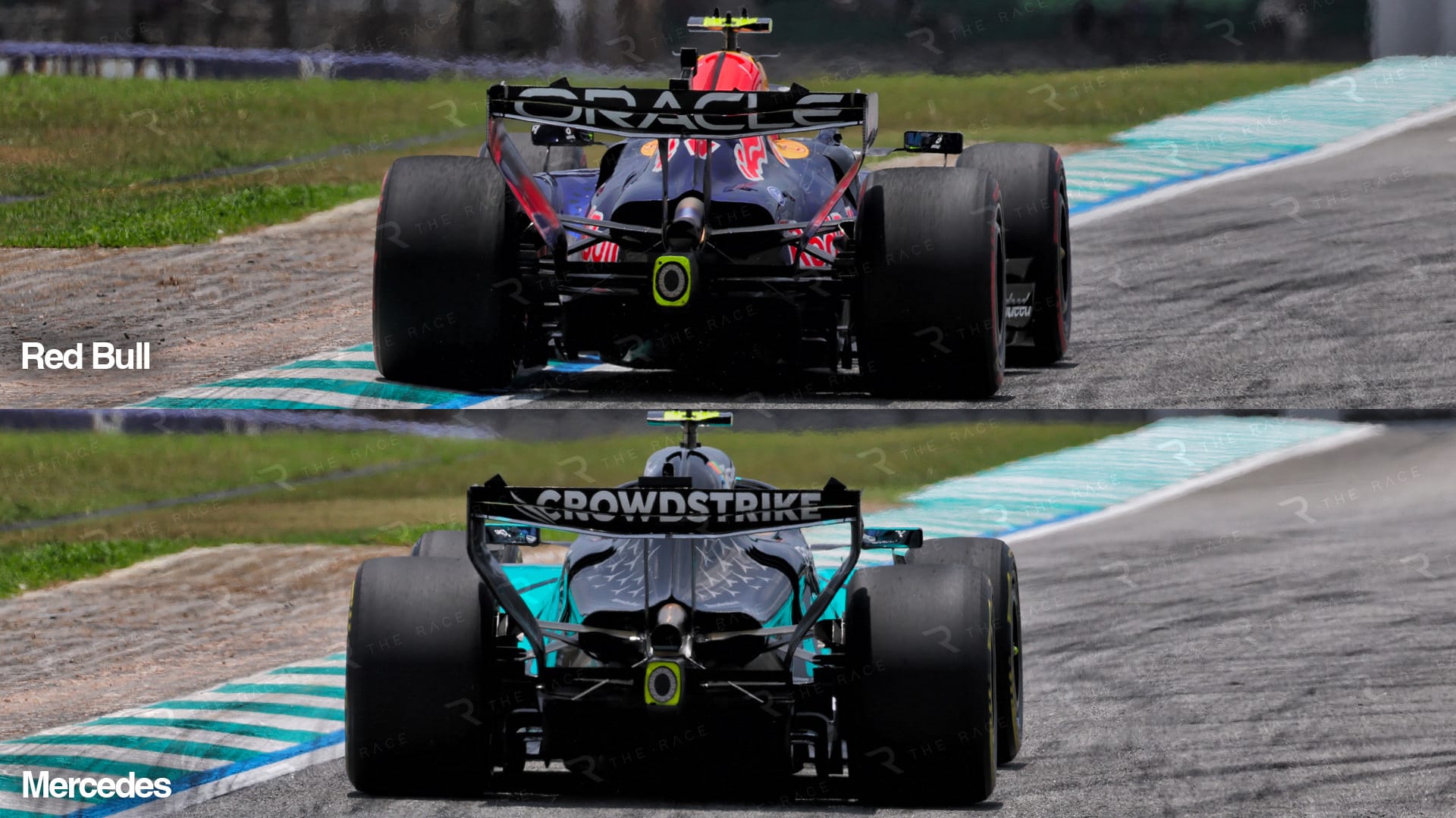
To be honest and upfront, I’m not saying either package is better than the other. To reach that conclusion would require countless hours of head-scratching and aerodynamic testing in both the windtunnel and CFD. Instead of just what keeps my ears apart, I would need a few (hundred) others to contribute.
This is mainly to show just what differences you can get from a very prescriptive set of regulations. Yes, those regulations don’t allow you to reinvent the wheel, but they still allow for some grey-matter scratching before you know what’s best, or hopefully best.